OpenTurbine guide
OpenTurbine 2.0 complete beginner user guide
Start with no electronics experience; finish with a wired, configured and thoroughly dry-tested ECU.
OpenTurbine is an experimental controller for turbine test projects. This guide explains the whole supported path, including what the words mean, what connects where, and what every current Config field does. It does not make an unknown turbine, sensor, driver, fuel system or ignition system safe. Obtain the manuals and limits for the exact parts you use, and have a competent person inspect the wiring before any fuel or ignition test.
Keep fuel disconnected, ignition energy disabled, starter/load power isolated, and the turbine unable to move while completing Parts 1–10. A browser STOP button is not an emergency stop.
Contents
- Words used in this guide
- What you need
- How the system is connected
- Wire the ECU power and emergency stop
- Wire inputs and sensors
- Wire outputs and actuators
- Install OpenTurbine and connect
- Describe the hardware in the dashboard
- Understand controllers and safety functions
- Configure all ECU settings
- Calibrate inputs and outputs
- Build startup and shutdown sequences
- Use control rules
- Dry-test the complete ECU
- Prepare for a first fueled test
- Operate, back up, update and diagnose
Part 1: Words used in this guide
You only need these basic ideas to begin:
- ECU means electronic control unit. Here it is the ESP32 board running OpenTurbine.
- GPIO means a numbered electrical pin on the ESP32. The Hardware page only offers pins valid for the selected board.
- Input is information entering the ECU: temperature, RPM, pressure, a switch, or a throttle command.
- Output is a low-power command leaving the ECU. It tells a separate driver, relay, ESC or servo what to do.
- Sensor measures something. Its raw electrical signal often needs a converter or conditioner before the ESP32 can read it.
- Actuator does something physical: a pump, starter, valve, igniter, fan or servo.
- Driver has two meanings in this guide. An electrical output driver carries load current; a USB driver lets Windows communicate with the ESP32.
- N1 is the gas-generator/core shaft speed. N2 is a separate free power-turbine/output shaft speed where fitted.
- TOT/EGT is turbine-outlet/exhaust gas temperature. TIT is turbine-inlet temperature. Use the measurement and limit specified by the engine documentation.
- ADC converts a safe analog voltage into a number. The ESP32 ADC pin must never receive more than its permitted voltage.
- PWM is rapid on/off switching used to request a proportional output. A servo/ESC signal is a different pulse format and must be selected as such.
- Active LOW means the function is active when the signal is connected to ground. Active HIGH means active when voltage is present.
- Pull-up gently holds an unconnected digital input HIGH. A switch can then connect it to ground to make it active LOW.
- Closed loop means the ECU measures the result and adjusts an output to reach a target. Open loop sends a fixed output without measuring the result.
- Fail-safe is the state selected for a missing signal or software fault. Independent emergency stop is separate hardware that removes hazardous energy even if the ECU has failed.
Part 2: What you need
Required for the normal supported path
- A Classic ESP32 board with at least 4 MB flash, or an ESP32-S3 DevKitC-1-compatible board with at least 8 MB flash. The universal S3 image works on 8 MB and 16 MB modules without requiring PSRAM.
- A Windows computer and a USB data cable. A charge-only cable will power the board but cannot install firmware.
- A clean regulated ECU power supply within the board maker’s limits, with a fuse.
- A multimeter and the datasheets for the board, every sensor, every converter and every output driver.
- Correct connectors, wire sizes, strain relief, enclosure, fuses and transient protection for the environment.
- A hardwired emergency-stop circuit that removes fuel or relevant load power independently of the ESP32.
Add only what the engine actually needs
Common minimum instrumentation is N1 speed plus TOT or TIT. Oil-lubricated systems commonly add oil pressure. The firmware supports many more inputs and outputs, but fitting every possible item does not automatically make a better system. Every added part creates another wiring, calibration and failure path.
Do not use solderless breadboards for a fueled or vibrating turbine installation. They are useful only for low-energy bench learning.
Part 3: How the system is connected
Click or tap the diagram to enlarge it.
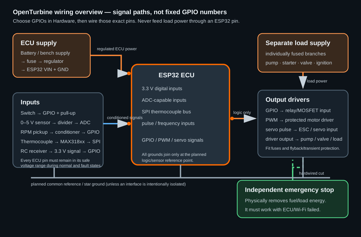
There are four paths to keep separate:
- ECU power: supply → fuse → regulator → ESP32 VIN and GND.
- Sensor signals: sensor → required conditioner/converter → selected ESP32 input GPIO.
- Output signals: selected ESP32 output GPIO → driver/ESC/relay input. The GPIO carries only a command.
- Load power: separately fused supply → emergency-stop/contact path where required → driver → pump, valve, starter or ignition load.
Use a deliberate star-ground or similarly engineered return scheme. Starter, pump and ignition current must not flow through the sensor ground path. If an interface is intentionally isolated, follow its isolation design and do not add a ground that defeats it.
Part 4: Wire the ECU power and emergency stop
4.1 Build the power path
- Read the exact ESP32 board’s VIN/5V and 3V3 limits. Do not guess from another board.
- With power off, connect the regulated supply positive through an appropriately rated fuse to the board input specified by its manufacturer.
- Connect the supply negative to the planned ECU ground point.
- Leave every sensor, driver and load disconnected.
- Set a current-limited bench supply conservatively, power the board, and measure its input and 3.3 V rail.
- Remove power before adding each new circuit.
Never feed external voltage into an unpowered ESP32 GPIO. It can back-power and damage the board.
4.2 Build the independent stop
The emergency stop must directly remove the energy that can keep fuel flowing or a hazardous load operating. A common pattern uses a normally closed fuel valve or a power contactor whose coil circuit passes through a latching emergency-stop button. The exact components and ratings depend on the system.
Test these cases without fuel:
- stop pressed while the ECU is running normally;
- ESP32 unplugged or frozen;
- Wi-Fi and browser unavailable;
- output driver signal wire shorted or disconnected; and
- power restored after a stop.
The safe result must not depend on code executing.
Part 5: Wire inputs and sensors
5.1 The rule for every input
Before connecting a signal to the ESP32, answer all five questions from its datasheet:
- What powers the sensor?
- What is the lowest and highest possible output, including a fault?
- Is it digital, analog voltage, pulse/frequency, RC PWM, SPI, 1-Wire, I²C or a load-cell bridge?
- Does it need a divider, pull-up, filter, comparator, isolator or converter?
- Which ground/reference must be shared?
Measure the conditioned output before attaching it to the GPIO. ESP32 GPIO uses 3.3 V logic and is not 5 V tolerant.
5.2 Typical wiring by electrical type
Click or tap this diagram to enlarge it. These four drawings show the exact meaning of power, ground and signal; replace the generic GPIO label with the pin you saved on the Hardware page.
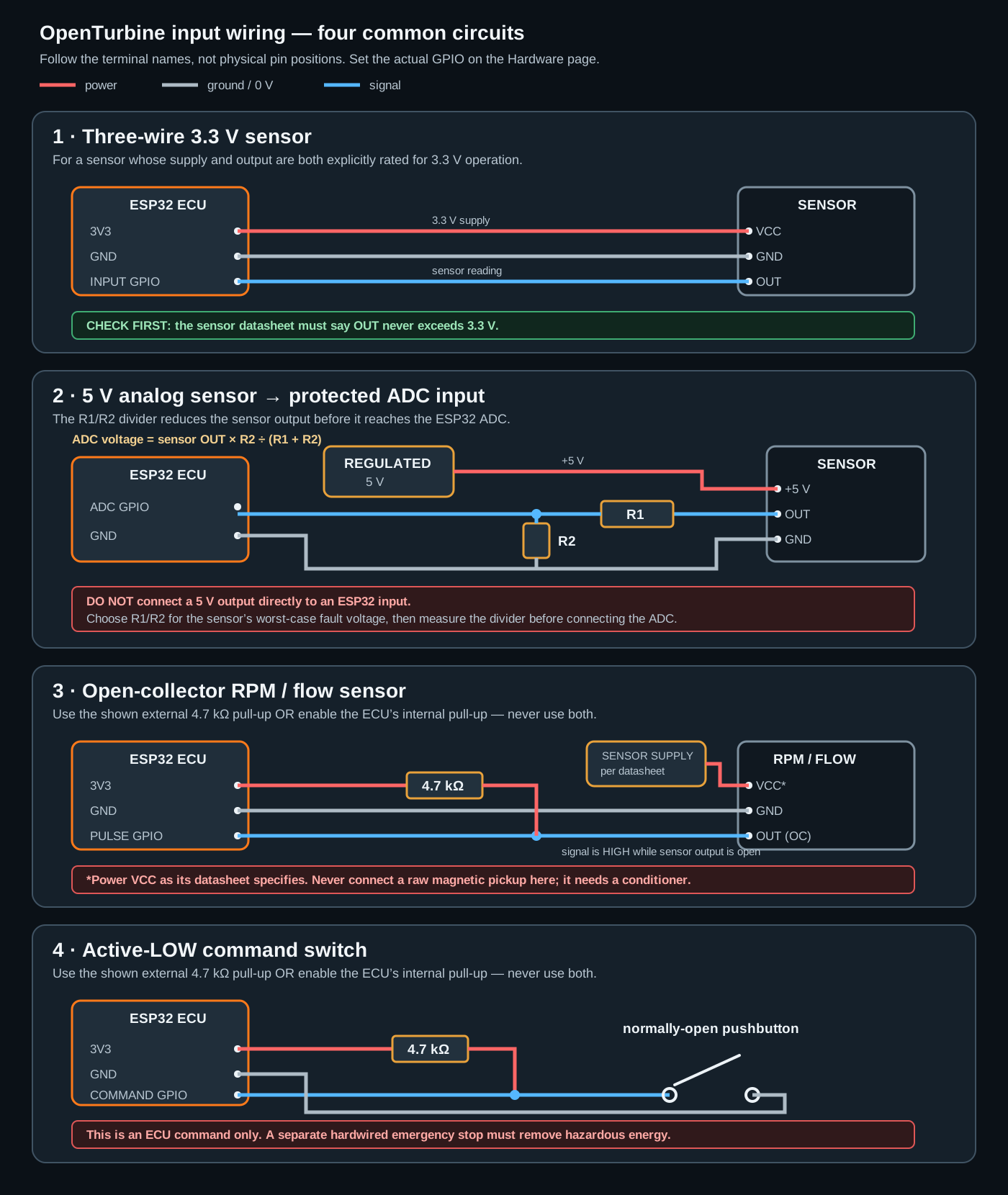
| Electrical type selected in Hardware | Connection pattern | Important fields |
|---|---|---|
| Digital switch | For the usual active-LOW arrangement: selected GPIO → switch → sensor ground; enable a pull-up. The input reads active when the switch closes. | GPIO, active polarity, input bias. Use an external resistor and protection for long/noisy wires. |
| Analog voltage / ADC | Sensor output → protection/filter and, if needed, voltage divider → ADC-capable GPIO. Sensor ground returns to the sensor reference point. | GPIO, minimum/maximum raw ADC counts, mapped engineering range. Calibrate with a trusted reference. |
| Pulse/frequency | Open-collector sensor: pull up to 3.3 V. Magnetic/variable-reluctance pickup: use a proper conditioner/comparator. Conditioner output → GPIO. | GPIO, pulses per revolution/litre/unit, frequency or engineering endpoints. Shaft-speed PCNT inputs default to a 5 µs glitch filter and derive their plausibility ceiling from twice the applicable hard shutdown speed. |
| RC PWM | Receiver signal must be 3.3 V compatible; receiver and ECU need a valid reference unless isolated. Do not power a receiver from an unsuitable pin. | GPIO, minimum/maximum pulse width, signal-loss timeout, calibrated command endpoints. |
| PWM duty input | Condition the external PWM to 3.3 V logic, then connect to the selected input GPIO. | GPIO and mapped endpoints. This reads duty/frequency; it is not a servo pulse unless RC PWM is selected. |
| MAX31855 / MAX31856 / MAX6675 | Thermocouple → matching converter terminals; converter VCC/GND → permitted supply/reference. Enable the shared SPI bus and choose SCK/MISO once; MAX31856 also needs shared MOSI. Each module needs its own CS GPIO. | Shared bus pins at the top of Hardware; interface type, unique CS, thermocouple type and polarity on the device card. |
| DS18B20 | VDD and GND as specified; DQ → selected GPIO with the required pull-up to the correct logic supply. | GPIO, discovered sensor/address behavior and resolution. The 10-bit default updates substantially faster than 12-bit. Keep the bus away from ignition noise. |
| NTC thermistor | Thermistor plus a known resistor form a voltage divider; divider midpoint → ADC GPIO. | GPIO, nominal resistance, beta/coefficient and calibration. Divider values must keep the pin safe. |
| HX711 | Load cell/bridge → HX711 inputs; HX711 data and clock → their selected GPIOs; power and grounding follow the module/load-cell specifications. | Data/clock pins, zero and scale calibration. |
| TCA9554 / TLA2528 / NAU7802 I²C | Connect every device to the configured shared SDA/SCL bus with suitable pull-ups and 3.3 V-compatible levels. The Hardware page discovers responding chips automatically. | Only connected devices can receive new assignments. TCA9554 provides binary I/O, TLA2528 analog inputs, and NAU7802 thrust/torque load-cell channels. |
Classic ESP32 note: use ADC1 GPIO 32–39 while Wi-Fi is active. GPIO 34–39 are input-only. ADC2 readings are unreliable while Wi-Fi is operating. On ESP32-S3, use only choices offered for that selected target; native USB and flash/PSRAM pins are not spare pins.
If an I²C chip is unplugged, its channels become unhealthy and its saved assignments are shown as Disconnected. Use Remove device and assignments to clear all channels and dependencies belonging to a permanently removed chip. Native ESP32 GPIO remains strongly recommended for turbine fuel, ignition, starter, and shutdown outputs because a disconnected TCA9554 can physically retain its last output latch.
5.3 Every available input purpose
The Purpose field tells the firmware how an installed channel may be used. The current code offers these purposes:
| Input purpose | What it does and how to use it |
|---|---|
| N1 speed | Primary core-shaft RPM. Used by startup checks, overspeed, flameout/surge logic, idle control, windmilling protection and logs. Wire only a clean conditioned pulse and set pulses/revolution. |
| N2 speed | Free power-turbine/output-shaft RPM. Enables N2 overspeed, N2 idle feedback, shaft power and the N2 governor. |
| Additional shaft speed | Extra speed channel for rules, custom sequencing and logs. It does not replace the primary N1 or N2 purpose. |
| TOT / EGT | Turbine-outlet temperature, normally through a supported thermocouple converter. Can be the primary engine-temperature safety source. |
| TIT | Turbine-inlet temperature. Use when the engine documentation specifies a TIT limit; never substitute a TOT limit. |
| Oil pressure | Feedback for oil protection and optional closed-loop oil-pump control. Wire and calibrate the exact transducer range. |
| Fuel pressure | Fuel-manifold feedback for diagnostics and optional low-pressure shutdown. |
| P1 / P2 / coolant pressure | Compressor inlet, compressor discharge and cooling-system measurements used for display, logging, rules and calculated behavior where supported. |
| Oil, coolant or intake temperature | Auxiliary temperature channels. Oil temperature can enable its dedicated shutdown; others are available to logging and automation. |
| Fuel flow | Pulse or analog flow measurement for consumption logs and rules. Enter the manufacturer's pulses/litre or calibrated mapping. |
| Main / scavenge oil flow | Separate flow feedback for the corresponding pump. Calibrate in L/min, enable monitoring on that pump's Hardware card, and test its minimum-flow threshold. Confirmed underflow warns by default; shutdown is a separate Config choice. |
| Main flame / afterburner flame | Dedicated combustion detectors. Main flame can confirm startup/flameout; AB flame can confirm afterburner light-off. |
| Torque | Analog, HX711, or NAU7802 measurement. NAU7802 calibration captures unloaded zero plus known force and lever arm. With N2 it supports shaft-power calculation; it is also available to rules. |
| Thrust | NAU7802 load-cell measurement calibrated from unloaded zero plus a known force or mass. Canonical display, telemetry, rules and logs use newtons. |
| Battery / bus voltage | Scaled ADC measurement for display, logs and undervoltage protection. A battery must never connect directly to an ADC pin. |
| Throttle input | Operator demand from analog, RC PWM, pulse-duty or another supported input. Calibrate low/high endpoints and signal-loss behavior. |
| Idle input | Separate idle/startup demand, usable as digital, analog, RC PWM, pulse or duty depending on the installation. |
| Digital interlock | General switch for rules and sequence conditions. |
| Inhibit-start | Prevents a start while the external inhibit is active. |
| Emergency-stop request | Requests ECU shutdown. Useful in addition to, never instead of, the hardwired energy-removing stop. |
| Fault switch | External equipment can request fault shutdown. |
| Low-oil / zero-oil switch | Discrete alternatives or supplements to an analog oil-pressure transducer for their corresponding protections. |
| Sequence gate | Physical permission/condition used by a Wait For Input sequence block. |
| Afterburner arm / command | Separate permission and fire-request switches for afterburner installations. |
| Reduced-power mode | Requests the configured output cap. |
| Generic automation input | Normalized digital, analog, pulse, RC or duty input for custom rules/sequence logic; it has no built-in engine meaning. |
Part 6: Wire outputs and actuators
6.1 Never power a load from a GPIO
An ESP32 GPIO can provide only a logic command. Use an interface rated for the real voltage, continuous current, starting/stall current, inductive energy, switching rate and fault conditions.
| Output driver selected in Hardware | Signal connection | Typical use |
|---|---|---|
| Relay / on-off | GPIO → 3.3 V-compatible protected relay/MOSFET driver input. Driver output switches the load supply. Fit appropriate coil/load suppression. | Normally closed fuel valve, contactor enable, solenoid, simple igniter enable. |
| PWM | GPIO PWM → protected motor/power driver command. The driver, not the ESP32, carries load current. | DC pump, fan, glow driver or proportional power stage. |
| Servo / ESC | GPIO signal → servo/ESC control input; reference grounds only as the interface requires. Load power comes from its separately rated supply. | Fuel-pump ESC, starter ESC, propeller pitch or nozzle actuator. |
6.2 Every available output purpose
| Output purpose | What OpenTurbine commands |
|---|---|
| Main fuel pump / throttle ESC | Primary proportional engine-power command. Used by sequences, throttle slew, idle control, governor and protections. Calibrate its minimum reliable command with fuel isolated. |
| Fuel shutoff | Normally closed main-fuel safety valve. It opens for fuel admission and closes on shutdown. Its de-energized state should be safe. |
| Starter | Relay, PWM driver or ESC demand used to spool the engine. |
| Starter enable | Separate contactor/enable for starter electronics that require enable plus proportional demand. |
| Oil pump | Fixed or pressure-controlled oil delivery, startup priming and windmilling protection. |
| Coolant pump / scavenge pump / cooling fan | Auxiliary pumping and cooling outputs usable from sequences and rules. Scavenge can continue into shutdown where configured. |
| Pilot / auxiliary fuel pump | Independent second fuel output for sequence/rule use. It does not automatically mirror main throttle. |
| Igniter / afterburner igniter / glow plug | Commands the appropriate external ignition or glow driver. The ESP32 never drives a coil or glow element directly. |
| Valve / solenoid | Bleed or other on/off valve through a rated driver. |
| Afterburner valve / pump | Dedicated afterburner fuel shutoff and delivery outputs used by AB sequences. |
| Air starter | Air-start valve through an on/off driver. |
| Pilot gas / start-fuel solenoid | Dedicated light-off fuel valve for an applicable combustion system. |
| Air / fuel purge valve | Valve that can be placed in a custom safe sequence. |
| Electric drain valve | Open/close output available to startup/shutdown sequences, Control Rules and standby Tools tests. Configure its physical polarity or endpoints in Hardware. |
| Variable nozzle / propeller pitch | Proportional servo/ESC output; propeller pitch can be the N2 governor's controlled output. |
| Generic automation output | Relay, PWM or servo output controlled by custom rules or sequence steps, with no built-in engine role. |
For every output, set a Power-on state / Boot safe demand and a Fault safe demand that are electrically safe. Verify actual polarity at the driver input and load terminals; a label in software cannot correct a wrongly wired active-low module.
Part 7: Install OpenTurbine and connect
If this ECU previously ran a pre-2.0 build, keep its engine file only as a reference and follow the v2 migration guide. Version 2.0 intentionally changed the hardware model and several startup/safety settings; recommission it instead of assuming an old file is safe.
- Download the guided Windows Setup Tool.
- Disconnect all load power. Connect exactly one intended ESP32 by USB.
- For a blank board choose Clean install / reinstall. It erases that board. For an existing working ECU, make a backup and choose Update and keep my setup.
- If the tool identifies a CP210x or WCH USB bridge without a COM port, accept only the matching driver it offers. If a COM port exists but the board does not respond, close serial monitors and follow the BOOT/RESET instructions.
- After installation, join the Wi-Fi network created by the ECU and browse to
http://192.168.4.1. - Complete the safety acknowledgement and first-run prompts.
If the Wi-Fi appears but the page does not, stay connected to that network and type the numeric address directly. See Troubleshooting if needed.
Part 8: Describe the hardware in the dashboard
The dashboard cannot discover ordinary wired sensors and actuators. You must describe exactly what you fitted.
8.1 Choose the board first
Open Hardware, select the exact Classic ESP32 or supported ESP32-S3 target, and save/reboot if requested. A GPIO number on one board is not automatically safe on another.
8.2 Add one channel at a time
- In Inputs, choose Add input and pick the preset matching the physical sensor or switch.
- In Outputs, choose Add output and pick the matching actuator.
- Complete the card fields described below.
- Resolve every red requirement, pin conflict or invalid-channel message.
- Save, let the ECU reboot, reopen Hardware, and compare the saved page with the physical wire list.
8.3 What every channel-card field means
| Field | What to enter |
|---|---|
| Display name / label | A short human-readable name shown in the dashboard and logs, such as “Main oil pressure”. Renaming it does not break stable references. |
| Stable ID | A short unique machine name such as oil_pressure_main. Set it once; rules, sequences and telemetry may refer to it. |
| Purpose | The built-in ECU meaning listed in Parts 5 and 6. This determines which safety, controller, sequence and rule options can use the channel. |
| Controller use / binding | Assigns the installed device to a core job such as primary N1 or main fuel output. Do not bind two devices to one exclusive role. |
| Electrical driver | The real signal type: digital, ADC, pulse, RC, PWM duty, thermocouple interface, relay, PWM or servo/ESC. It must match the wiring. |
| GPIO / CS / CLK / MISO / MOSI / data | The physical board pins used by that interface. Choose only offered pins and use each exclusive pin once. Shared SPI clock/data lines are allowed only where the UI explicitly accepts the shared bus. |
| Active polarity | Whether HIGH or LOW means active. For an active-LOW switch to ground, select active LOW and a pull-up. |
| Input bias | Internal pull-up, pull-down or none. Use only when electrically appropriate; never enable both. |
| Minimum/maximum raw value | The measured electrical endpoints: ADC counts, frequency or pulse width. Minimum must be below maximum. |
| Minimum/maximum mapped value | The engineering quantity those raw endpoints represent, such as 0–10 bar or 0–100%. |
| Pulses per revolution/litre/unit | The sensor's real pulse count from its datasheet or calibration. A wrong value produces a proportionally wrong reading. |
| PWM frequency and resolution | Must match the receiving driver. Higher resolution can limit available carrier frequency. |
| Duty/pulse at 0% and 100% | The actual PWM duty or servo pulse produced at the two command endpoints. These are electrical endpoints, not the pump's minimum-running calibration. |
| Minimum non-zero / reliable command | Smallest nonzero command that reliably keeps an applicable motor/driver moving. Find it cautiously in Calibration/Tools. |
| Output polarity / reverse | Reverses the electrical interpretation. Verify with a meter before connecting a load. |
| Power-on / boot-safe demand | Command applied during initialization and after some tests. Choose the physically safe state. |
| Fault-safe demand | Command used when the ECU enters fault handling. This is not a replacement for a de-energized safe design. |
| Current-sensor fields | ADC GPIO, sensor mV/A, zero-current voltage and overcurrent limit for an attached current sensor. Calibrate zero with the load off. |
Part 9: Understand controllers and safety functions
9.1 Controllers
A controller continuously changes an output based on a measurement. Enable it only after its sensor and output work independently.
| Controller | How it works | When to enable it |
|---|---|---|
| Oil pressure loop | Compares measured oil pressure with the active target and changes oil-pump demand. Gain controls reaction strength; deadband prevents constant tiny corrections; fallback handles a failed sensor. | After the oil-pressure input is calibrated and the proportional oil-pump output, plumbing and safe fallback demand are proven. |
| Smooth fuel/throttle movement | Limits how quickly the main fuel output opens or closes. It also supports gradual limit protection behavior. | Normally enabled for a proportional main-fuel output. Set opening/closing times from controlled tests, not examples. |
| Automatic idle control | Measures one selected N1, N2, P1, or P2 source and adjusts fuel within configured bounds to hold idle. N1/N2 is the normal proven method; pressure control is experimental and has separate target, deadband, and disengagement settings. | Only after manual/fixed idle behavior is stable, the selected feedback is calibrated, and fuel limits are safe. |
| Automatic N2 speed control | Compares N2 with its target and changes main fuel or proportional propeller pitch. Pitch control increases load to restrain speed. | Only on an appropriate two-shaft system with verified N2, output direction, travel limits and conservative gains. |
9.2 Safety functions
Enabling a checkbox does not prove the protection. You must force a safe simulated fault and confirm the response.
| Safety | Trigger and prerequisite |
|---|---|
| N1 overspeed | Hard shutdown above Maximum N1 Speed; requires primary N1. |
| N2 overspeed | Independent hard shutdown above Maximum N2 Speed; requires N2. |
| Turbine gas overtemperature | Watches the startup-specific selected TOT/TIT limit during STARTUP and the normal hard limit during RUNNING. A zero startup limit inherits the normal limit. |
| Low oil pressure | Shutdown after configured low-pressure behavior; requires oil pressure or a low-oil switch. |
| Zero oil pressure | Detects effectively absent oil pressure; requires oil pressure or a zero-oil switch. |
| Flameout | Declares combustion loss using the selected flame, N1, or EGT evidence after its confirmation time. EGT evidence means temperature is below its threshold and falling, or is falling faster than the configured rate. |
| Hot start | Blocks START when selected turbine temperature is already above the pre-start limit. The normal/startup overtemperature guard then protects the active start. |
| Oil temperature high | Shutdown above the oil-temperature limit; requires that input. |
| Fuel pressure low | Shutdown below the running fuel-pressure threshold; requires fuel-pressure input. |
| Battery undervoltage | Fault behavior below the configured bus-voltage threshold; requires a scaled, calibrated voltage input. |
| Surge / compressor instability | Uses rolling N1 variance to detect oscillation. It requires a clean N1 signal and engine-specific validation to avoid false trips. |
The Hardware page disables protections whose required input is not fitted. After enabling a protection, go to Config and enter its threshold. A value of zero disables several thresholds; read each field explanation carefully.
Part 10: Configure all ECU settings
10.1 Safe order
- Open Config only after Hardware saves without errors.
- Select Essentials first. Enter limits from the exact engine, sensor and actuator documentation.
- Use Changed to review every edit. Yellow fields are not saved yet.
- Use Explore all features to inspect or preconfigure features whose required hardware/controller is absent. Amber-bordered tuning values save normally but remain inactive until Hardware satisfies the displayed prerequisite. Enable switches and choices for missing hardware remain locked, so Explore cannot arm a feature unexpectedly. Search also reveals unavailable settings; neither Explore nor Developer Mode bypasses a missing physical prerequisite.
- Save one related group at a time and read the save recap.
- Reopen the page and confirm values survived the reboot/save.
Never copy “typical”, example or preset values into a fueled turbine without verifying them. Units matter: RPM, milliseconds, percent, pressure and °C/°F are not interchangeable.
10.2 Complete source-matched field reference
The expandable sections below document every field currently rendered by data_src/config.html. This list is generated from the dashboard schema rather than maintained as a second handwritten list. If a field is unavailable, Hardware has not provided its prerequisite.
152 fields in 22 sections. This reference is generated from the same schema that renders the ECU Config page, so names and explanations match the current code.
Engine Protection Limits 11 fields
| Dashboard field | What it controls |
|---|---|
| Maximum N1 Speed (RPM) | Hard overspeed limit for the gas-generator/core shaft. Used only when an N1 sensor is fitted. |
| Maximum N2 Speed (RPM) | Independent hard shutdown limit for the free power-turbine/output shaft. This is separate from gradual N2 throttle pullback. Used only when N2 overspeed safety is enabled in Hardware. |
| Minimum Running N1 Speed (RPM) | Lowest N1 speed accepted after startup. Falling below it causes an underspeed shutdown. Set 0 to disable this independent underspeed check when N1 is informational only. |
| Primary Engine Temperature | Temperature used for over-temperature protection, hot-start prevention, cooldown, throttle reduction, and flame confirmation. |
| Outlet Temperature Limit (TOT) | Hard limit for turbine-outlet temperature. Active only when TOT is the primary engine temperature. 0 disables this limit. |
| Inlet Temperature Limit (TIT) | Hard limit for turbine-inlet temperature. Active only when TIT is the primary engine temperature. 0 disables this limit. |
| P1 High-Pressure Shutdown | Stops fuel when P1 rises above this pressure for the configured confirmation time. 0 disables the P1 high-pressure trip. |
| P2 High-Pressure Shutdown | Stops fuel when P2 rises above this pressure for the configured confirmation time. 0 disables the P2 high-pressure trip. |
| Shaft-Torque Hard Shutdown (Nm) | Stops fuel when measured shaft torque remains above this independent limit for the configured confirmation time. 0 disables the torque hard trip. |
| Pressure / Torque Hard-Trip Confirmation (ms) | P1, P2 or torque must remain above its hard limit for this long before shutdown. 0 is immediate. |
| Temperature Warning Margin | Distance below the active hard temperature limit where warnings and gradual throttle reduction begin. |
Oil System 15 fields
| Dashboard field | What it controls |
|---|---|
| Running Low-Pressure Shutdown | The ECU shuts the engine down if oil pressure stays below this value while running. |
| No-Pressure Shutdown Threshold | Detects a stopped pump, broken line, or disconnected sensor when pressure is effectively zero. |
| Low-Oil Confirmation (ms) | Oil pressure must remain below the running shutdown value for this long before shutdown. 0 is immediate. |
| Near-Zero Oil Confirmation (ms) | Catastrophic near-zero oil pressure must persist for this time. Keep this shorter than the normal low-oil confirmation. |
| Increase Oil Pressure with Throttle | Raise the oil-pressure target as throttle increases. Leave disabled for one constant running target. |
| Normal Running Oil Pressure | Target at idle and throughout running when throttle-based pressure is disabled. Keep it above the low-pressure shutdown value. |
| Full-Throttle Oil Pressure | Target at full throttle when throttle-based pressure is enabled. |
| Oil Pressure Response Gain | How strongly pump output reacts to pressure error. Higher responds faster but can oscillate. Technical name: proportional or P gain. |
| Minimum Automatic Pump Output (%) | Lowest output used by automatic pressure regulation. Startup steps can still command a higher output. |
| No-Correction Pressure Band | No small pump corrections are made while pressure is within this distance of the target. Technical name: deadband. |
| Continuous Pump Overcurrent Shutdown Delay (ms) | With oil-pump current sensing fitted, warn immediately and shut down only if current remains above the Hardware current limit for this long. |
| Low Oil-Flow Confirmation Delay (ms) | How long a monitored main or scavenge pump may remain below its own Hardware minimum-flow value before the ECU confirms a flow fault. |
| Shutdown on Confirmed Low Oil Flow | Off (default): report a warning and keep running. On: a confirmed low/no-flow fault requests an engine shutdown. Configure and test each pump flow meter in Hardware before enabling this. |
| Pressure-Sensor Fault Delay (ms) | How long invalid oil-pressure feedback is tolerated before automatic pressure regulation stops and the fixed fallback output below takes over. |
| Fixed Pump Output After Pressure-Sensor Failure (%) | Open-loop pump output used after oil-pressure feedback has remained invalid for the fault delay above. This is separate from windmilling protection. |
Throttle Response 4 fields
| Dashboard field | What it controls |
|---|---|
| Full Opening Time (ms) | Time for the fuel/throttle output to move from 0 to 100%. A larger value opens more gently. |
| Full Closing Time (ms) | Time for the fuel/throttle output to move from 100% to 0. A smaller value closes faster. |
| Maximum Idle Fuel Output (%) | Fuel/throttle output when the idle control is at its maximum. The low end comes from Calibration > Minimum Reliable Fuel-Pump Output. |
| Low-Throttle Sensitivity | Softens response near idle while preserving full travel. 0 is linear; 1 is maximum softening. Technical name: throttle expo. |
Gradual Fuel Limit Protection 25 fields
| Dashboard field | What it controls |
|---|---|
| Gradual N1 Limit Protection | Automatically reduce fuel as N1 approaches its configured limit. |
| Begin N1 Throttle Reduction (RPM) | N1 speed where gradual fuel reduction begins. |
| Full N1 Throttle Reduction (RPM) | N1 speed where the gradual reduction reaches full authority. Hard shutdown protection remains separate. |
| Gradual N2 Limit Protection | Automatically reduce fuel as the power-turbine/output shaft approaches its speed limit. |
| Begin N2 Throttle Reduction (RPM) | N2 speed where gradual fuel reduction begins. |
| Full N2 Throttle Reduction (RPM) | N2 speed where gradual reduction reaches full authority. |
| Gradual Temperature Protection | Automatically reduce fuel as the selected engine temperature approaches its limit. |
| Begin Temperature Reduction | Temperature where gradual fuel reduction begins. |
| Full Temperature Reduction | Temperature where gradual reduction reaches full authority. |
| Gradual P1 Pressure Protection | Reduce fuel as P1 approaches its configured full-reduction value. |
| Begin P1 Fuel Reduction | P1 pressure where gradual fuel reduction begins. Set it below the full-reduction pressure and below any independent P1 hard shutdown. |
| Full P1 Fuel Reduction | P1 pressure where gradual protection reaches its configured maximum fuel reduction. The independent P1 shutdown limit can still cut fuel completely. |
| Gradual P2 Pressure Protection | Reduce fuel as P2 approaches its configured full-reduction value. |
| Begin P2 Fuel Reduction | P2 pressure where gradual fuel reduction begins. Set it below the full-reduction pressure and below any independent P2 hard shutdown. |
| Full P2 Fuel Reduction | P2 pressure where gradual protection reaches its configured maximum fuel reduction. The independent P2 shutdown limit can still cut fuel completely. |
| Gradual Shaft-Torque Protection | Reduce fuel as measured shaft torque approaches its configured full-reduction value. |
| Begin Torque Fuel Reduction (Nm) | Measured shaft torque where gradual fuel reduction begins. Set it below the full-reduction torque and below any independent torque hard shutdown. |
| Full Torque Fuel Reduction (Nm) | Measured shaft torque where gradual protection reaches its configured maximum fuel reduction. The independent torque shutdown can still cut fuel completely. |
| Minimum Fuel During Gradual Protection (%) | Lowest fuel/throttle output allowed by gradual protection. Emergency protection may still command less. |
| Limit-Protection Strength | How strongly fuel is reduced near a limit. 1.0 is normal; higher is more aggressive and may cause oscillation. |
| Gradual Limit-Protection Method | Reactive control uses current N1/N2/P1/P2/EGT/torque readings. Predictive control also uses each signal rate of change to estimate where it is heading and reduce fuel before an overshoot. |
| Limit Prediction Time (ms) | How far ahead Advanced mode projects speed, pressure, selected TOT/TIT, and torque. Typical starting point: 1000-2000 ms. |
| Near-Limit Full Opening Time (ms) | Slower full-opening time used near the predicted speed limit. Larger values make the approach gentler. |
| Begin Prediction This Far Below Limit (RPM) | Distance below the gradual limit where the ECU starts slowing fuel increases. 0 chooses this distance automatically. |
| Speed-Change Smoothing (0-1) | Smooths the estimated rate of RPM change. Lower values are steadier but slower; higher values react faster but pass more sensor noise. |
Reduced-Power Mode 1 fields
| Dashboard field | What it controls |
|---|---|
| Maximum Fuel Output (%) | Shared main-fuel cap when Reduced-Power Mode is turned on from Tools or a configured switch, or automatically because feedback used by an enabled protection/controller becomes unhealthy. A high value also permits higher fuel after that safety feedback is lost. |
Automatic Idle Control 23 fields
| Dashboard field | What it controls |
|---|---|
| Idle Feedback Source | N1/N2 speed feedback is the normal proven approach. Pressure feedback is available for experimental turbine arrangements and requires careful stand validation. |
| Idle Target (N1/N2) (RPM) | Used when the selected feedback source is N1 or N2. |
| Idle Target (P1/P2) | Used when the selected feedback source is P1 or P2. |
| Fuel Increase Time (ms) | How quickly automatic idle control may increase fuel. |
| Fuel Decrease Time (ms) | How quickly automatic idle control may reduce fuel. |
| No-Correction Band (N1/N2) (RPM) | Used for an N1/N2 feedback source. |
| Stop Controlling Above (N1/N2) (RPM) | Used for an N1/N2 feedback source. |
| No-Correction Band (P1/P2) | Used for a P1/P2 feedback source. |
| Stop Controlling Above (P1/P2) | Used for a P1/P2 feedback source. |
| Minimum Fuel Range Multiplier | Scales the calibrated minimum reliable fuel-pump output to set the controller floor. |
| Maximum Fuel Range Multiplier | Allows the controller extra fuel authority above the configured maximum idle output. |
| Long-Term Correction Strength | Removes a persistent speed error caused by changing accessory load. 0 disables this correction. Start small: 0.05–0.15. Technical name: integral gain. |
| Maximum Long-Term Correction | Limits how much fuel the long-term correction may add or remove. 0.10 means 10% of the available fuel range. |
| Idle-Control Method | Standard control corrects present speed error. Predictive control learns the steady idle output and briefly reduces fuel during a fast return from high speed so RPM settles without hanging high. |
| Fast-Deceleration Entry Above Target (RPM) | Predictive control activates when RPM is at least this far above the idle target. |
| Fast-Deceleration Fuel Reduction (%) | How far below the learned steady-idle output fuel may drop during a fast return to idle. |
| Idle Speed Prediction Time (ms) | How far ahead predictive idle control estimates shaft speed. |
| Settled Speed Band (RPM) | The ECU considers idle stable and learns the required fuel output while RPM is within this distance of target. |
| Speed Error for Full Correction (RPM) | RPM error where automatic idle control reaches its maximum correction rate. |
| Maximum Fuel Correction Increase (%/s) | Fastest rate at which predictive idle control may add fuel. |
| Maximum Fuel Correction Decrease (%/s) | Fastest rate at which predictive idle control may remove fuel. |
| Steady-Idle Learning Speed (0-1) | How quickly the learned steady-idle fuel output adapts after speed settles. Smaller values are steadier. |
| Maximum Speed Change While Learning (RPM/s) | The ECU learns steady-idle fuel only while RPM is changing more slowly than this value. |
Combustion & Startup Protection 8 fields
| Dashboard field | What it controls |
|---|---|
| Safety Check Interval (ms) | How often general safety conditions are evaluated. Hard overspeed and current-delay timing run independently. Restricted to 10-250 ms so protection cannot be delayed by configuration. |
| Combustion-Loss Confirmation Time (ms) | How long the selected signal must indicate flameout before the ECU declares a fault. |
| How Combustion Loss Is Detected | Signal used to decide that combustion has been lost while RUNNING. A flame sensor is the most direct evidence; N1 is the preferred fallback. EGT-only detection is available when neither is fitted. |
| N1 Flameout RPM | For N1-source flameout: declare flameout if N1 stays below this RPM. 0 uses Min RPM. This is delayed by Flameout Delay. |
| Low EGT for Flameout | For EGT-source flameout: combustion loss is suspected when selected EGT is below this value and still falling while RUNNING. The condition must persist for the Combustion-Loss Confirmation Time. 0 disables this low-temperature condition. |
| Rapid EGT Fall for Flameout | For EGT-source flameout: also suspect combustion loss if selected EGT falls faster than this rate, even before it reaches the low-EGT threshold. Default 50 °C/s. 0 disables this rapid-fall condition. |
| Pre-Start EGT Maximum | Blocks START when selected EGT is already above this value. This check occurs before fuel or ignition is commanded; it does not trip on the normal ignition temperature rise. 0 disables the hot-engine start interlock. |
| Maximum EGT During Startup | Hard selected-EGT shutdown limit while the startup sequence is active. 0 uses the normal TOT/TIT hard limit, so startup remains protected. Set a separate value only when the engine manufacturer permits a different transient startup limit. |
Automatic Flameout Relight 7 fields
| Dashboard field | What it controls |
|---|---|
| Attempt Automatic Relight | After combustion loss, try to restore flame before committing to shutdown. |
| Ignition Output to Use | Output energized during the relight attempt. |
| How Successful Relight Is Confirmed | Signal that confirms combustion has returned and allows ignition to turn off. |
| Minimum N1 to Fire Relight Ignition (RPM) | The ECU will not energize automatic relight below this healthy N1 speed or below Minimum Running N1, whichever is higher. If N1 falls below the effective floor during an attempt, ignition is cut and the engine shuts down. Choose a speed that proves adequate self-sustaining airflow. |
| N1 Recovery Confirmation (RPM) | For N1 relight confirmation: ignition stays on until healthy N1 reaches this explicit speed. Normally set this at or above the minimum firing speed and above the N1 flameout trigger. |
| EGT Recovery Rise | For EGT relight confirmation: igniter stays on until selected EGT rises this much above the temperature at relight start. 0 prevents EGT-rise confirmation. Set too low and EGT noise/throttle changes can false-confirm; too high can reject a real relight. Verify on a real start. |
| Relight Timeout (ms) | Maximum continuous relight ignition time after a flameout. If combustion is not restored, ignition is cut and the engine shuts down. A normal combustor usually relights within 1,000-2,000 ms; increase only from verified engine tests. 0 = no timeout (not recommended). |
ECU Runtime 1 fields
| Dashboard field | What it controls |
|---|---|
| ECU Loop Target Hz | Main control-loop target frequency. Default 400 Hz. Lower values reduce CPU use; higher values improve control granularity but increase load. Recommended range: 200-500 Hz. Takes effect after a reboot. |
External Instrument Cluster Display 4 fields
| Dashboard field | What it controls |
|---|---|
| N1 Warn RPM | N1 warning zone start on cluster gauge (yellow). 0 = auto (RPM Limit × 0.9). N1_MAX comes from Engine Limits → RPM Limit |
| N2 Warn RPM | N2 RPM warning threshold for cluster display |
| EGT Warn | Selected engine-temperature warning threshold for cluster status. 0 = auto (selected EGT limit minus safety margin). |
| Oil Warn | Oil pressure warning status code threshold. 0 = auto (running minimum) |
Pulsed Starter Assist 5 fields
| Dashboard field | What it controls |
|---|---|
| Enable Pulsed Starter Assist | Allow StarterSpin to use low-speed pulses. Requires a servo/PWM starter and healthy N1 feedback. Relay/on-off starters are intentionally unsupported. |
| Assist Starter Output (%) | Starter demand during each ON pulse. Verify this output with the STANDBY-only Tools test before attempting a start. |
| Assist Until N1 Speed (RPM) | Once healthy N1 reaches this value, pulsing finishes for the current StarterSpin block and ordinary starter control continues. Normally set this below the StarterSpin target. |
| Pulse ON Time (ms) | How long the starter remains energized during each assist pulse. |
| Pulse OFF Time (ms) | Rest time between assist pulses. |
Windmilling Oil Protection 4 fields
| Dashboard field | What it controls |
|---|---|
| Shaft to Monitor | Choose which shaft can automatically request protective oil flow. |
| Start Oil Pump Above (RPM) | Oil protection starts when the selected shaft exceeds this speed while the ECU is in standby. Keep it below that shaft's maximum speed or the protection can never activate. |
| Windmilling Fixed / Minimum Pump Output (%) | Used as the fixed windmilling output when the pressure target is 0, or as the minimum pump output while pressure is regulated. |
| Optional Windmilling Oil Pressure Target | Above 0: use the normal automatic oil-pressure regulator to hold this target, with the fixed/minimum output as its floor. At 0: command only the fixed output. Pressure mode requires a fitted oil-pressure sensor and Oil pressure loop enabled in Hardware. |
Manual Relight and Cooldown Override 4 fields
| Dashboard field | What it controls |
|---|---|
| Cooldown Temperature Target | Cooldown completes after the selected engine temperature falls below this value. |
| Cooldown Skip Hold (ms) | Hold START+STOP simultaneously for this long during SHUTDOWN to force-skip the cooldown and go to STANDBY, even if selected EGT is still above the cooldown target. |
| START Relight Output | Which configured ignition output is held on while START is held during RUNNING. |
| Igniter on START (running) | Fire igniter while START button is held during RUNNING — manual relight aid. Disable if accidental button presses are a concern. |
RPM Sensor Fault Detection 2 fields
| Dashboard field | What it controls |
|---|---|
| Maximum RPM Change Rate | Maximum plausible shaft acceleration or deceleration, expressed as a fraction of that shaft's configured RPM limit per second. Example: 0.40 with a 100,000 RPM limit allows 40,000 RPM/s (4,000 RPM between 100 ms samples). Jump checking starts only after the previous accepted reading is above 500 RPM, so the first rise from zero does not fault. |
| Zero Readings Before Fault | Number of consecutive zero readings required before a running RPM sensor is declared stuck at zero. |
Afterburner — Ignition Conditions 4 fields
| Dashboard field | What it controls |
|---|---|
| Min N1 RPM | AB will not attempt ignition below this shaft speed (compressor needs sufficient airflow). |
| Max N1 RPM | AB will not attempt ignition above this shaft speed (high compressor pressure can prevent AB lighting). 0 = disabled. |
| Max EGT for Light | Do not attempt ignition if selected EGT exceeds this (engine already too hot). 0 = disabled. |
| Throttle Trigger % | Throttle demand percent that triggers AB when source is set to Throttle. |
Afterburner — Ignition Method 6 fields
| Dashboard field | What it controls |
|---|---|
| Use Torch | Spike main fuel demand through the turbine section to push burning exhaust into the AB duct. Configure torch timing in the fields below. |
| Use AB Igniter | Fire the dedicated afterburner igniter installed in Hardware during the ignition window. Can be used alone or with torch. |
| Torch Spike % | Main fuel pump extra demand % during the torch window. Higher = more fuel pushed through. Typical: 20–40%. |
| Torch Duration (ms) | How long to hold the fuel spike before cutting back. Typical: 300–600 ms. |
| Torch EGT Cut | Cut torch spike if selected EGT exceeds this during ignition. Protects turbine from over-temperature. 0 = disabled. Typical: 900-1000 °C / 1650-1830 °F. |
| Light-Up Pump % | AB fuel pump demand used while the light-up sequence is trying to establish a confirmed flame. |
Afterburner — Flame Confirmation 5 fields
| Dashboard field | What it controls |
|---|---|
| Light-up Evidence | How light-up is assessed. Timed assumption provides no evidence that fuel has ignited and should be used only when the installation has no usable flame or EGT feedback. |
| EGT Rise | Minimum selected EGT rise required to confirm ignition (EGT Rise mode). Typical: 20-50 C. Too low can false-confirm on noise/throttle changes; too high can reject a real light. Verify on a real start. |
| EGT Rise Window (ms) | Time window in which the required EGT rise must occur (EGT Rise mode). Typical: 1500-3000 ms. |
| Unverified Timed Delay (ms) | Delay before continuing without verifying flame. This is not flame confirmation. Typical starting point: 1000-2000 ms, verified on a restrained test setup. |
| Confirmation Timeout (ms) | Overall deadline for flame confirmation. Exceeding this triggers an AB fault and shuts down the afterburner. Typical: 3000-5000 ms. |
Afterburner — Running 7 fields
| Dashboard field | What it controls |
|---|---|
| Pump Command Source | Choose how AB pump flow is commanded while lit. Dedicated AB Input uses the ADC or servo-PWM AB input configured in Hardware. Note: if the AB input was not in use when the ECU booted, switching to Dedicated AB Input needs a reboot before the input is read. |
| Afterburner Fuel Pump Min % | Minimum afterburner fuel-pump demand for a variable command source. With a missing servo-PWM afterburner input, demand fails to this minimum. |
| Afterburner Fuel Pump Max % | Maximum afterburner fuel-pump demand. Fixed Max Output holds this value while the afterburner is running. |
| Main Fuel Offset % | Add this to main throttle demand while AB is running (extra air/fuel for compressor). 0 = none. |
| Stabilize Hold (ms) | Hold time after confirmed ignition before declaring the afterburner Running. Typical: 500-2000 ms. |
| Stabilize Max EGT | AB faults if selected EGT exceeds this during the stabilize hold. 0 = disabled. |
| Running Flame-Loss Delay (ms) | When flame-sensor verification is selected, shut down only the afterburner if its flame signal is absent or unhealthy for this long while Running. Default 1000 ms. The main engine keeps running. |
Auxiliary Protection 7 fields
| Dashboard field | What it controls |
|---|---|
| Oil Temp Limit | Maximum oil temperature before fault shutdown. 0 = disabled. Typical limit: 120–150 °C / 250–300 °F depending on oil grade. |
| Oil-Temperature Confirmation (ms) | High oil temperature must persist for this time before shutdown. |
| Minimum Running Fuel Pressure | Low fuel pressure fault threshold during RUNNING. 0 = disabled. Typical: 0.5–2.0 bar / 7–30 PSI depending on pump type. |
| Fuel-Pressure Confirmation (ms) | Low running fuel pressure must persist for this time before shutdown. |
| Battery Min (V) | Battery / bus undervoltage fault threshold. 0 = disabled. Set ~0.5 V below your minimum expected loaded voltage. Typical: 10.5 V for 3S LiPo. |
| Bus-Voltage Confirmation (ms) | Low battery or bus voltage must persist for this time before shutdown. |
| Experimental Surge Detection (RPM²) | Experimental statistical N1-instability detector over a 10-sample rolling window, not an RPM limit. It requires tuning from recorded stable and surge data for this exact engine. 500,000 RPM² corresponds to about 707 RPM standard deviation. 0 disables it. |
Automatic N2 Speed Control 5 fields
| Dashboard field | What it controls |
|---|---|
| Target N2 RPM | Power turbine (N2) speed setpoint for the governor. Set to your rated output shaft RPM. 0 = governor disabled. In prop-pitch mode the governor adds propeller load to hold this speed, so set it to your rated power-turbine RPM — too low can over-load and stall the core. |
| No-Correction Speed Band (RPM) | The controller makes no correction while N2 is within this distance above or below the target. A small band prevents hunting. Typical: 200–500 RPM. |
| Fuel Change at 1,000 RPM Error (%/s) | Fuel correction rate produced by a 1,000 RPM error outside the no-correction band. Example: 25 means fuel changes 25 percentage points per second at that error. Start around 10-25 and increase only while checking for hunting. |
| Pitch Change at 1,000 RPM Error (%/s) | Requested propeller-pitch correction rate at a 1,000 RPM error. A nonzero value selects pitch-primary control when a proportional pitch actuator is fitted. Actual movement is also limited by Full Propeller-Pitch Travel Time. |
| Full Propeller-Pitch Travel Time (s) | Shortest allowed time for the pitch actuator to travel through its full range. This prevents abrupt load changes. 0 allows immediate movement. Typical: 1–5 s. |
Glow Plug Preheat 3 fields
| Dashboard field | What it controls |
|---|---|
| Preheat Duration (ms) | Time to ramp the glow plug from 0 to maximum duty before ignition. Longer = more heat soak. Typical: 8,000–15,000 ms. |
| Preheat Peak Command (%) | Peak glow command during the preheat ramp. PWM glow uses this as duty percent; relay glow turns ON for any nonzero command. Typical PWM value: 60–90%. |
| Hold Command (%) | Glow command held after preheat completes. PWM glow uses this as duty percent; relay glow stays ON for any nonzero hold command. Typical PWM value: 20–40%. |
RC / Servo Signal Loss Detection 1 fields
| Dashboard field | What it controls |
|---|---|
| Signal-Loss Timeout (ms) | Marks a receiver input invalid when no valid pulse arrives in time. A lost operator-throttle signal returns main fuel toward the calibrated minimum output; STOP still performs the immediate fuel cut. |
Part 11: Calibrate inputs and outputs
Calibration makes a displayed number match reality. Do it in STANDBY or FAULT, with hazardous energy isolated.
- Open Calibration and confirm it shows only fitted hardware.
- Start with raw readings. A disconnected sensor should not look like a believable safe value.
- Apply a known low reference, capture/enter the low point, and record the physical value.
- Apply a known high reference, capture/enter the high point, and record the physical value.
- Test one or more points between them. If the middle is wrong, the sensor may be nonlinear or the electrical type may be incorrect.
- Save, reboot, and repeat the check.
Specific checks:
- N1/N2: compare several speeds with an independent tachometer. Correct pulses/revolution first.
- TOT/TIT: verify thermocouple type, polarity, connector metals, converter and probe location. Compare ambient and a controlled reference.
- Pressure: zero only while safely depressurized, then compare with a trusted gauge at multiple pressures.
- Voltage/current: compare with a meter at several loads; verify the divider ratio and current-sensor zero.
- Throttle/idle/AB input: capture true low and high endpoints, then test signal loss and reversed travel.
- Main fuel/oil/starter proportional outputs: test the command signal into a meter or disconnected driver first. Find minimum reliable behavior only in a suitably safe rig.
Part 12: Build startup and shutdown sequences
A sequence is an ordered list. Each block either performs an action, waits for a condition, waits for time, or checks a condition. The editor hides blocks whose required hardware is absent and explains each block with its ? button.
12.1 Beginner startup order
Do not copy this blindly; make it match the engine. A common logic pattern is:
- Build Oil Pressure (OilPrime): runs the oil pump and waits for pressure, or uses a timed fixed output if no pressure sensor exists.
- Starter Spin to Light-Off Speed (StarterSpin): enables/ramps the starter and waits for the configured light-off N1.
- Igniter On / Pre-Heat: energizes the selected ignition or glow output.
- Fuel Open / Fuel Pulse: admits the configured starting fuel.
- Confirm Combustion: uses FlameConfirm or TempConfirm; never leave light-off unverified merely because a timer expired.
- Spool / Modified Idle / Fuel Pump Idle: increases fuel toward the idle-entry condition.
- Verify Stable Idle (SafetyHold): confirms RPM/oil conditions before RUNNING.
Use Timed Delay only when time itself is the correct requirement. Wait For Input is for an installed permission switch. The output action blocks—Igniter, starter enable, starter, oil/scavenge pump, air starter, cooling fan, bleed valve, auxiliary fuel pump and throttle set—command the corresponding fitted actuator directly.
12.2 Beginner shutdown order
- Immediate Cut: zeroes throttle, closes fuel, and disables ignition/starter immediately.
- RPM Drop: waits for N1 to fall below the configured threshold.
- Cooldown Spin: uses starter/oil behavior to cool where the engine requires it.
- Wait TOT Cool: holds until the selected temperature is below its target if appropriate.
- Final Stop: waits for zero N1, cuts the main oil pump and preserves configured scavenge behavior.
Verify that STOP removes fuel immediately. Cooling, purge or scavenge actions may continue only as deliberately required. Test web STOP, loss of throttle/RC, a simulated sensor fault and the independent hardwired stop separately.
12.3 Every block field
- Block name/type identifies the behavior.
- Condition is what must become true before a “while” block exits.
- Demand / duty / percent is the normalized actuator command.
- Threshold / target is the sensor value the block is trying to reach or cross.
- Timeout is the maximum wait. Read whether expiry causes continue, abort or fault; these are intentionally different outcomes.
- Run on entry/exit side actions switch selected actuators when a sequence or block boundary is crossed.
- Custom block steps either set a fitted actuator or delay. A custom condition compares a fitted input with a threshold. Keep custom blocks small enough to reason about.
Run the full startup and shutdown sequence repeatedly with no fuel and ignition energy disabled.
Part 13: Use control rules
Control rules are small automations outside the main sequence. Each output may have one enabled rule.
Threshold rule
Choose an input, above or below, a threshold, hysteresis, on value and off value. Example: a fan turns on above 100 °C with 5 °C hysteresis; it stays on until temperature falls to 95 °C. Hysteresis prevents rapid chatter near the threshold.
Mapping rule
Choose an input minimum/maximum and an output minimum/maximum. The ECU maps linearly between them and clamps outside the range. Use it for a verified proportional relationship, not a safety shutdown.
Fields common to both
- Enabled makes the rule active.
- Input is a fitted registry channel.
- Output is the one actuator the rule owns.
- States limits the rule to Starting, Running and/or Shutdown; All States removes that limit.
- Off value is commanded when the rule is outside its states or its input becomes unavailable.
Fault handling returns authority to the output’s hardware-safe state. Rules do not override fault safety.
Part 14: Dry-test the complete ECU
“Dry” means no fuel can reach the engine and ignition cannot create hazardous energy. Use a meter, indicator lamp or safe dummy load before a real actuator.
- Compare every Hardware GPIO with a physical wire-by-wire checklist.
- On the dashboard, move or stimulate each input and verify direction, units, range and plausible failure behavior.
- Open Tools → Test settings and reduce test duration/demand to a conservative value.
- Test one output at a time: logic pin first, then driver with no load, then a safe dummy load, then the real isolated actuator where appropriate.
- Confirm active-high/low behavior, power-on state, end-of-test state and fault-safe state.
- Run a complete dry startup. Confirm every condition and timeout.
- Run normal STOP, fault shutdown and loss-of-signal tests.
- Cut Wi-Fi/browser access and prove the independent stop still removes hazardous energy.
- Power-cycle at unexpected points and confirm no output energizes unexpectedly.
- Download a backup and the dry-test logs.
Do not proceed while any pin conflict, unavailable dependency, implausible reading, unexplained reboot, unexpected output pulse or failed stop test remains.
Part 15: Prepare for a first fueled test
A first fueled turbine test is beyond beginner electronics assembly. Have the complete installation reviewed by someone competent in the turbine, fuel, electrical and test-cell hazards.
Before fuel is connected, verify all of these:
- limits come from authoritative documentation for this exact engine and probe location;
- fuel and oil plumbing is restrained, routed safely and leak-tested;
- pumps, starter, valves and igniters use rated drivers, wiring and fuses;
- every safety input is calibrated and its fault response was forced safely;
- the turbine is restrained in a suitable outdoor/test-cell exclusion zone;
- fire suppression, hearing/eye protection and remote observation are ready;
- another competent person is present where the risk assessment requires it; and
- the physical emergency stop was tested immediately before the attempt.
Stop for any unexpected temperature, RPM, oil, vibration, fuel, wiring, actuator or controller behavior. Do not continue merely because the ECU has not declared a fault.
Part 16: Operate, back up, update and diagnose
Normal operation
Observe the engine itself, independent instruments and dashboard. Do not rely on Wi-Fi or a browser remaining connected. After a run, inspect the event log and session CSV for maximums, faults and sensor dropouts.
Backups
In Tools, download the complete engine file before major changes and before every update. It contains hardware, calibration, sequences, rules and Wi-Fi credentials. Store it securely and remove credentials before sharing. Logs are separate downloads.
Updates
Use Update and keep my setup for a working controller. Use clean install only for a blank board, deliberate erasure or recovery. Do not interrupt power while firmware or web assets are being installed. Read the release notes first.
Useful fault report
Record the board target, OpenTurbine version, fitted channel list, engine state, active sequence block, exact expected behavior and exact observed behavior. Include sanitized engine backup and logs where appropriate. Setup Tool diagnostics are under %LOCALAPPDATA%\OpenTurbine\SetupTool\logs.
Use symptom-based troubleshooting or open Setup Help. Do not share Wi-Fi credentials or sensitive installation details publicly.